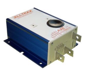
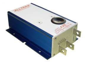
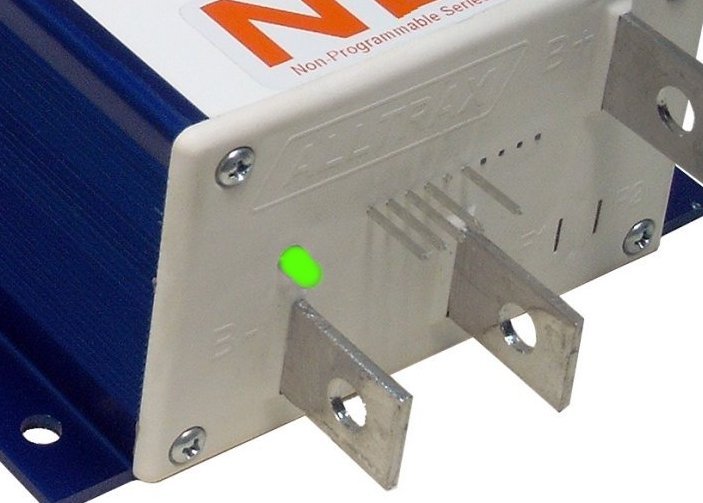
AXE Performance series and permanent magnet motor controllers

The AXE product line is used with Series Wound and Brushed Perm-Magnet Motors. These units drive golf cars, scissors lifts, boom trucks, Neighborhood electric vehicles, and a variety of other applications.
Features include:

  • Programmable via RS232 comm port using PC or Laptop
  • Integrated anodized heat-sink with multi bolt pattern for flexibility
  • Fully encapsulated epoxy fill – environmentally rugged design
  • Available in 300 through 650 amp Performance versions
  • Advanced MOSFET power transistor design for excellent efficiency and power transfer
  • ½ Speed reverse option and “Plug Brake” options available

SPECIFICATIONS

Model 2434 2444 4834 4844 7234 4845 4855 4865 7245
 

Model Size

xxx4

6.5” Heatsink

Xxx5

8.5” Heatsink

Battery Voltage 12-24V 24-48V 24-72V 24-48V 24-72V
Current Limit  


300A


400A


300A


400A


300A


400A


500A


650A


450A

30Sec Rating
2 Min Rating
5 Min Rating 200A 350A 200A 300A 200A 350A 400A 350A
1 Hour Rating 135A 200A 135A 150A 125A 175A 250A 250A 200A
Voltage Drop (*) @ 100Amp <0.30V <0.10V 0.30V <0.13V <0.16V <0.18V <0.09V <0.08V <0.11V

Note: The last digit in the AXE model number denotes heat sink size. See mechanical drawings below.
>xxx4 replaces the Curtis 1204 short heat sink at 6.5” in length (165.1mm)
>xxx5 replaces the Curtis 1205 long heat sink at 8.5” in length (215.9mm)

MODEL BREAKDOWN

Model number breakdown, for example the { AXE4834P } is broken down as:

  • AXE – Family name
  • 48 – First two digits = Battery String Voltage (two digits)
  • xx3x – third digit = amperage, 3=300 Amp model
  • xxx4 – fourth digit = Case size small heat-sink
  • “P” model – Denotes Plug Break, “M” denotes Momentary

Product Features

  • 30-60 VDC (48V models) (60VDC MAX)
  • 60-90 VDC (72V models) (90VDC MAX)

Operating Frequency: 18KHz

Control voltage range for Key Switch (KSI), Throttle and Reverse inputs:

  • 24-48 VDC Nom, (48V models) 60 VDC Max
  • 24-72 VDC Nom, (72V models) 90 VDC Max

Reverse Horn Output: 50mA sink max

Standby Current (Powered Up): <35mA

Throttle Input:

  • ITS (inductive)
  • Resistive 0-5K ohm (+/-10%) (2-wire and 3-Wire)
  • Resistive 5K-0 ohm (+/-10%)
  • 0-5Volt
  • 6-10Volt

Operating Temperature: -25C to 75C, 95C shutdown

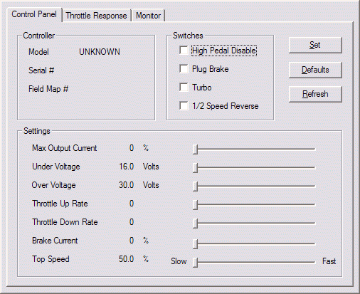
Adjustments via Controller Pro software:

  • Throttle acceleration/deceleration rate and map profile
  • Armature current limit
  • Brake current limit
  • Under / Over voltage shutdown
  • Half Speed Reverse
  • High Pedal Disable
  • Plug Brake

Control

Mechanical Drawings

Short Heatsink

DOWNLOAD DIAGRAM

Long Heatsink

DOWNLOAD DIAGRAM

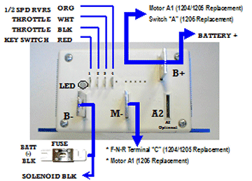
Product Wiring Connections

AXE Wiring Diagram:

An example of the inputs and outputs are shown. Click on the image to enlarge. This diagram is very generic example, please see our Documentation Page for the many various configurations this product can be used in.

VISIT DOCUMENTATION PAGE

LED Status Indicator

The LED located on the front of the unit provides status of the units operation and used for troubleshooting.

The LED Blink Codes occur at power up, the number of green blinks indicates the throttle configuration:

  • 1 Green LED flash = 0-5 kohm resistive
  • 2 Green LED flashes = 5K-0 ohm resistive
  • 3 Green LED flashes = 0-5 Volt
  • 4 Green LED flashes = EZ-GO inductive (ITS)
  • 5 Green LED flashes = Yamaha 0-1K ohm resistive
  • 6 Green LED flashes = Taylor-Dunn 6-10.5 Volt
  • 7 Green LED flashes = ClubCar 5k-0 ohms, 3-wire throttle

Normal display status:

  • Solid Green: Controller ready to run
  • Solid Red: Controller in programming mode (using Controller Pro)
  • Solid Yellow: Controller throttle is wide open, controller is supplying max output, and is not in current limit.

Troubleshooting:

Error code display: # of RED blinks indicates any error conditions that might exist:

  • 1 Red = Throttle Position Sensor Over Range. Check for open wires.
  • 2 Red = Under Temperature. Controller below -25C
  • 3 Red = HPD. Throttle hasn’t gone to zero during this power on cycle.
  • 4 Red = Over Temperature. Controller over 95C
  • 5 Red = Not used
  • 6 Red = Battery Under Voltage detected. Battery V < under voltage slider
  • 7 Red = Battery Over Voltage detected. Battery V > over voltage slider