An Advanced Motor Controller for Today’s Demanding Markets

  • 12 to 48 or 12 to 72 volt models
  • 300, 400, 500, 600 amp models
  • User personality switch input
  • Flexible USB programming
  • Integrated heat sink mounts on any suitable surface
  • Solenoid Control for Main DC Control
  • Standard 4-hole OR 2-hole mounting
  • Optional Universal-Mount Adapter for No Drill Install
  • Auto-throttle calibration for smooth operation
  • Hi-Reliability Optional Fan panel (500 & 600 Amp models include the fan)
DOWNLOAD SPEC SHEET

Instructables lesson on controlling motor speed

Controlling Motor Speed

(SR48600 Shown)

FEATURES/OPTIONS

Hi-Perfomance 32bit CPU

Throttle control for smooth operation compatible for most types of vehicle throttles.

Unsurpassed control with user adjustable from smooth to neck snapping wild!

Windows XP through Windows 10
  • Free software on web site
  • Simple Set-Up
  • User Friendly Controls
  • Note: Not compatible with WIN-8 RT (tablet)
5/16″ Terminals
  • B+ = POS – Battery + Motor Positive
  • B- = NEG – Battery Negative
  • J9 = M- Motor Minus Output
  • J7 & J8 = Not Used
  • SS 5/16″ hardware included
Customer Connections

Color Coded Quick Terminals:

  • RED = Key Switch
  • BLK = Solenoid Neg Control
  • BLUE – Reverse
  • GREEN – User Personality switch
  • Active Solenoid control RELAY Relay Coil Driver!
  • J4 + J5 = Isolated Throttle Inputs
  • USB Programmable using Alltrax Toolkit
Optional Universal Mount

The universal mounting adapter allows for a no drill installation on most carts with 3 and 4 hole bolt patterns.

The solenoid mounting bracket is used to mount the solenoid over the top of the controller in EZ-GO carts and custom applications.


Add to Cart

$25.00$36.00Select options

Hi-Reliability Fan Panel

Optional panel for hi-temp areas for 300 and 400 amp models, fan panel included in 500 and 600 amp models. Easy to replace fan panel uses a floating dual bearing design for many years of service in harsh environments. 12v fan replaceable with simple tools.

Add to Cart

$43.00Add to cart

ALLTRAX FN1 User Controls

The SR has one User input called a personality switch.

  • FN-1 provides interactive Speed + Acceleration control for mild street to wild performance.
  • Alltrax Toolkit can be used to set the range of these parameters to suite your needs.
  • Speed and Acceleration can be linked or separated using Alltrax Toolkit software setup.
LEARN MORE ABOUT FN

MECHANICAL PICTURES / DRAWINGS

SR

  • 5Dx9Wx3H-INCH
  • 300 amp
  • 400 amp
  • 500 amp

SR controllers ordered for EZ-GO come with the Universal Mounting Kit, solenoid mounting bracket and hardware.

The universal mounting kit allows for a no drill installation and allows you to attach the solenoid mounting bracket.

NOTE: Universal Adapter shown in RED for clarity.

Color of adapter shipped is “Alltrax Blue”

SR

SR Dimensions
Download Diagram
SR Drill Template
Download Diagram

Install PDFs

EZ-GO DCS
Download Diagram
Yamaha Install
Download Diagram
Club Car DS Install
Download Diagram

SPECIFICATIONS

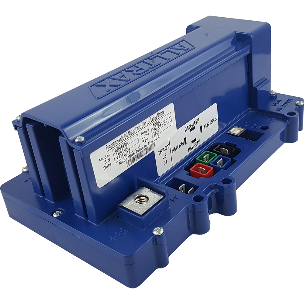
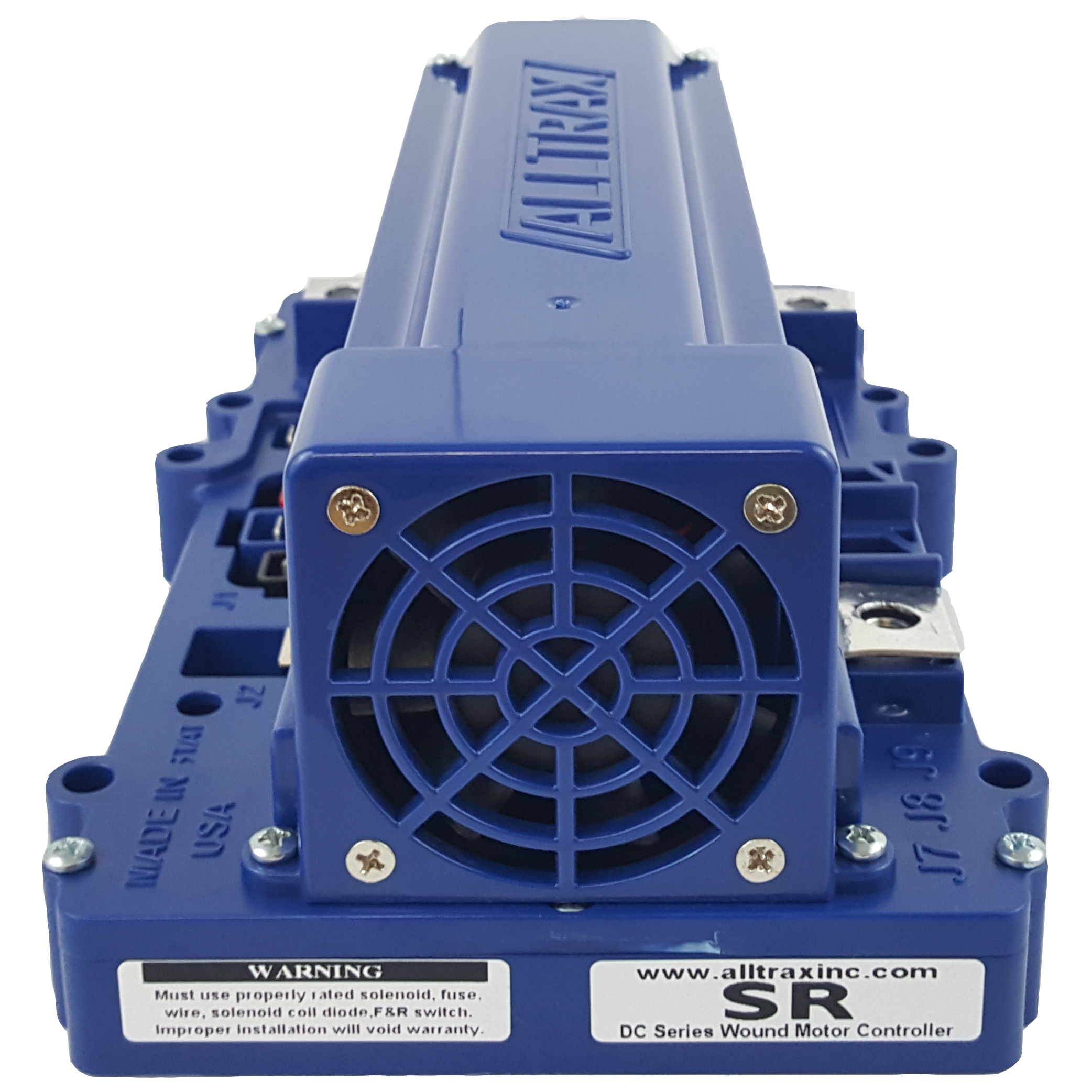
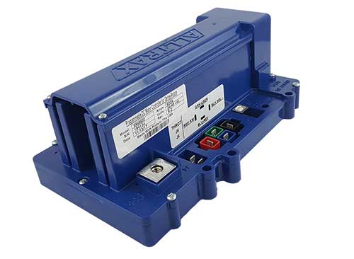
Type: DC “Series Wound” Motor Controllers

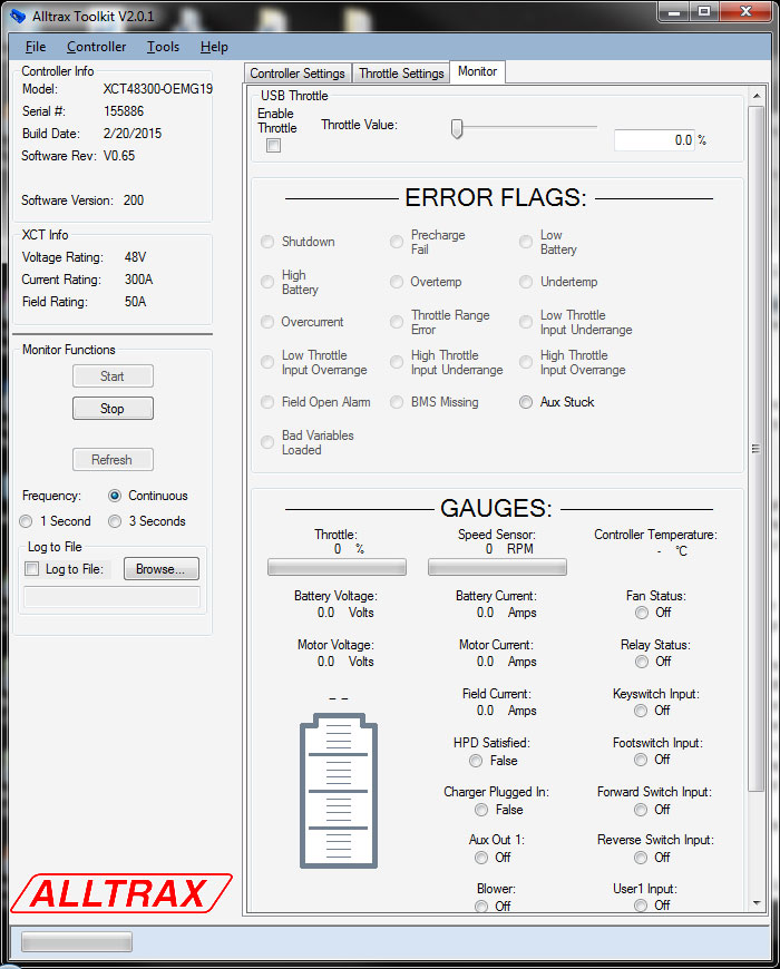
Overvoltage/Undervoltage shutdown: adjustable,

  • 8-60 VDC (48V models) (60VDC MAX)
  • 8-90 VDC (72V Models) (90VDC MAX)

Operating Frequency: 18kHz

Voltage drop @ 100 amps: <o.18V

Control Voltage: Key Switch (KSI), Reverse (REV) and Personality Switch (USER):

  • SR48xxx: 12-48V Nominal Battery Pack Voltage, 62VDC Max
  • SR72xxx: 12-72V Nominal Battery Pack Voltage, 92VDC Max

Standby Current (Powered Up): <35mA (nom)

Reverse sense pin current: <0.02A (20mA)

Relay SOLENOID drive output current: 5amp peak, 1.0A Continuous

Throttle Input:

  • ITS (inductive, E-Z-GO)
  • 0-1K Yamaha
  • Resistive 0-5K ohm (+/-10%) 2-wire and 3-Wire
  • Resistive 5K-0 ohm (+/-10%) Club Car
  • 0-5Volt
  • 6-10.5Volt (Taylor Dunn)
  • Absolute mode (Precision control for industrial applications)

Operating Temperature: -20 C to 85 C, Shutdown @ 95 C

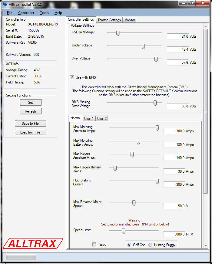
Adjustments via Alltrax Tool-Kit Software:

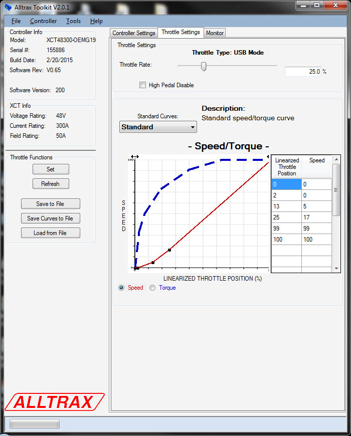
  • Throttle acceleration / deceleration rate and map profile
  • Armature current limit
  • Under / Over voltage shutdown
  • Half Speed Reverse
  • High Pedal Disable
Download Spec Sheet
SR Features:
  • All units 5/16” Stainless Steel hard ware (Included)
  • USB 2.0 compatible for programming user setting
  • ABS+PC510 Flame resistant thermal plastic
  • All copper heat sinks for superior thermal transfer
  • Sealed epoxy UL-94-VO / 5VA flame rating (Best in the industry)
  • High Efficiency fan for 500 & 600amp models (optional for 400amp)
  • FN-1 box compatible for user speed & acceleration control

Model Breakdown

Whats the Secret Decoder Ring?

SR-48300

Model number breakdown, for example the { SR – 48300 } is broken down as:

  • 48xxx – First two digits denote voltage, 24 – 48V or 24 – 72V models
  • 300 – Last three digits = amperage, 300 Amp model, 500=500amps (at 2 minutes)

Product Manuals and Diagrams

OPERATING MANUALS

SR Operators Manual
Download Manual
Alltrax Toolkit Software
Download Latest Version
Alltrax TOOLKIT Instruction Manual
Download Manual

WIRING DIAGRAMS

EZ-GO TXT
Download Diagram
EZ-GO Pre-1994
Download Diagram
Club Car
Download Diagram
Yamaha
Download Diagram
Generic Series No Reverse
Download Diagram
Generic Series with Reverse
Download Diagram
Generic Series Changeover
Download Diagram
Perm Mag
Download Diagram
Perm Mag No Reverse
Download Diagram

APP GUIDES

SR Club Car
Download APP Guide
SR EZ-GO
Download APP Guide
SR Yamaha
Download APP Guide
AXE-DCX-SPM
to SR & XCT
Cross Reference
Download APP Guide
SR-SPM Filter Kit Installation
Download APP Guide
SR Throttle Wiring
Download APP Guide

ALLTRAX TOOLKIT SOFTWARE

Using a standard USB printer cable to connect to the XCT, SR or SPM you can make simple changes to configure the controller to your needs.

Monitor output with a laptop and save the data to your hard drive. Troubleshooting or modifying vehicle can be examined in real time!

LED Status Indicator

The LED located on the front of the unit provides status of the units operation and used for troubleshooting.

The LED Blink Codes occur at power up, the number of green blinks indicates the throttle configuration:

  • 1 Green LED flash = 0-5 ohm resistive
  • 2 Green LED flashes = 5k-0 ohm resistive
  • 3 Green LED flashes = 0-5 Volt
  • 4 Green LED flashes = ITS Inductive E-Z-GO
  • 5 Green LED flashes = 0-1K ohm resistive, Yamaha
  • 6 Green LED flashes = 6-10.25 Volt, Taylor-Dunn
  • 7 Green LED flashes = 5k-0 ohms, 3-wire, ClubCar
  • 8 Green LED flashes = Reserved for future use
  • 9 Green LED flashes = PUMP Mode (toggle on-off ramp to 100% output)
  • 10 Green LED flashes = USB Comm-throttle
  • 11 Green LED flashes = Absolute throttle

Normal display status:

Solid Green: Controller ready to run
Solid Yellow_ Controller throttle is wide open, controller is supplying max output, and is not in current limit

Troubleshooting:

The XCT-SRX controllers ERROR codes are different than the AXE and DCX products. Please note the Error code display: # of GREEN and RED blinks indicates any error conditions that might exist:

Critical:

  • 1-GRN (+) 1-RED LED flash = Over Current/Short Circuit
  • 1-GRN (+) 2-RED LED flash = Battery Under Voltage
  • 1-GRN (+) 3-RED LED flash = Battery Over Voltage
  • 1-GRN (+) 4-RED LED flash = Over Temp (Check connections)
  • 1-GRN (+) 5-RED LED flash = Motor Field OPEN alarm (Check connections)
  • 1-GRN (+) 6-RED LED flash = Pre-Charge Failure

Status Indicator:

  • 2-GRN (+) 1-RED LED flash = Under Temp (below -20C)
  • 2-GRN (+) 2-RED LED flash = Not Used (Reserved)
  • 2-GRN (+) 3-RED LED flash = High Throttle Over-range (note 1)
  • 2-GRN (+) 4-RED LED flash = High Throttle Under range (note 1)
  • 2-GRN (+) 5-RED LED flash = Low Throttle Over range (note 2)
  • 2-GRN (+) 6-RED LED flash = Low Throttle Under range (note 2)

Note 1: High Throttle range is the “full pedal position”

  • The throttle could be faulty
  • Wiring/connectors
  • Incorrect throttle set in the program
  • Otherwise, Clear throttle auto-calibration and try again

Note 2: Low Throttle range is the pedal “at rest OFF pedal position”

  • The throttle could be faulty
  • Wiring/connectors
  • Incorrect throttle set in the program
  • Otherwise, Clear throttle auto-calibration and try again

Note 3: Uncalibrated throttle

  • May occur when an XCT, SR, SPM or SPB controller is auto-calibrated to one electric car throttle, then moved to another electric car – or, a new throttle is replaced.
  • Clear throttle auto calibration and try again

Advanced controller have a multitude of inputs and outputs. A sequence of Green+Red provides more alarm codes without counting past 6 flashes (which is difficult to do).

There is a pause between these alarm sequences always starting with GREEN.

Group 1: 1-Green + Red alarm code is a Critical Alarm
Group 2: 2-Green + Red alarm code is a condition that may inhibit or cause the controller to stop, but is not a hard fault, rather a condition that requires attention.
Group 3: 3-Green + Red alarm code is an uncalibrated throttle, clear the throttle calibration and try again. The program may also have a fault or loaded or updated incorrectly. Contact Alltrax Customer support for troubleshooting Bad Vars.

Tech-Talk: Throttle Range
When the throttle is pressed and foot-switch closes and records the “zero position” of the throttle. The controller remembers the highest input and stores this as 100% throttle.
This allows throttles that are “not manually calibrated”, production variances, or slightly old and worn to provide excellent low end control and always hit 100% throttle.
This learning curve is “adaptive” with built in fail safes which means – the advanced XCT knows what the range is suppose to be for a give throttle.
So if a 0-5K resistive throttle is measuring “Out Of Range” an alarm will alert the user to verify the mechanical issues to prevent an unsafe condition.