STOCK or OEM Products For used for SERIES Wound or Permanent Magnet Electric Motors

Wound Motors, (Field and Armature are in series). These units are designed specifically for factory equipped golf cars.

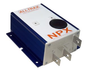
Customers demanded higher quality after-market replacement with a warranty instead of “REBUILT USED Controllers”. Alltrax stepped up and designed a NEW product with a NEW warranty, the NPX Non-Programmable controllers. A cost effective solution to replace your aging or damaged stock controller without buying a “rebuilt controller”.

Features Include:

  • Factory Programmed (These are not field programmable by the customer)
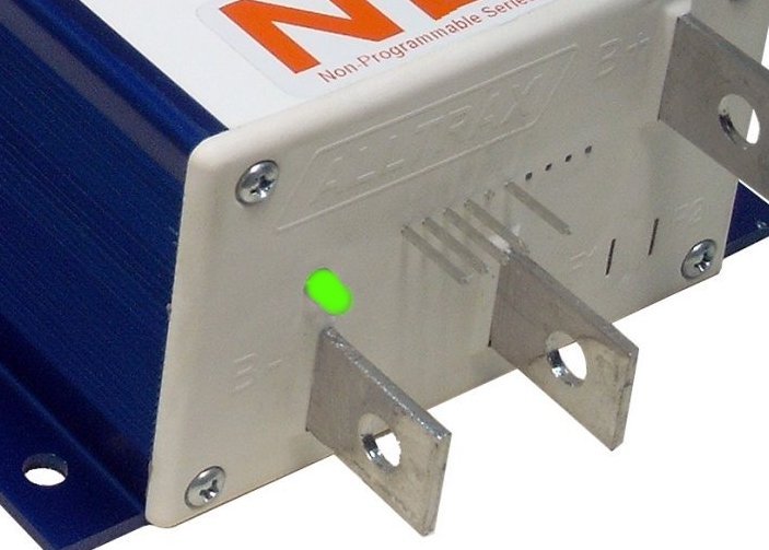
  • Integrated anodized heat-sink with multi bolt pattern for flexibility
  • Fully encapsulated epoxy fill – environmentally rugged design
  • Advanced MOSFET power transistor design for excellent efficiency and
  • ½ Speed reverse

SPECIFICATIONS

These units are designed for OEM (Original Equipment Manufacturers) stock replacement controllers for stock cars with stock motors only. With a peak current rating they are not designed for lifted or high performance vehicles. The design follows the motor manufacturers current and power.

For a high performance controller application – Please order our AXE motor controllers.

Model 4834 4844
Model Size

6.5” Short Heatsink

Battery Voltage 24-48V
Current Limit (Peak) 300 Amp
2 Min Rating 275 Amp 300 Amp
1 Hour Rating 125 Amp 135 Amp
Voltage Drop(*) @100Amp <0.30V <0.13V

Note: The last digit in the NPX model number denotes heat sink size. See mechanical drawings below. >xxx4 replaces the Curtis 1204 short heat sink at 6.5” in length (165.1mm)

MODEL BREAKDOWN

Model number breakdown, for example the { NPX4834-EZ } is broken down as:

  • NPX – Family name
  • 48 – First two digits = Battery String Voltage (two digits)
  • xx3x – third digit = amperage, 3=300 Amp model
  • xxx4 – fourth digit = Case size small heat-sink
  • “EZ” – Identifiers stipulates the EZ-Go throttle and wiring configuration

Product Features

  • 30-60 VDC (48V models) (60VDC MAX)

Control Voltage range: KSI, Throttle Reverse inputs

Control voltage range; Key Switch (KSI), Throttle and Reverse inputs:

  • 24-48 VDC, 60 VDC Max

Reverse Input: 50mA sink max

Standby Current (Powered Up):

  • ITS (inductive)
  • Resistive 0-5K ohm (+/-10%) (2-Wire)
  • Resistive 5K-0 ohm (+/-10%) (3-wire)

Throttle Ramp Rates: 1.5 Seconds

Operating Temperature: -25C to 75C, 95C shutdown

Adapter Circuits: See Product Page – Golf Car Adapters

Mechanical Drawings

Heatsink

DOWNLOAD DIAGRAM

Product Wiring Connections

NPX Wiring Diagram:

An example of the inputs and outputs are shown.  Click on the image to enlarge.  This diagram is also shown on the NPX Mini-Manual.

DOWNLOAD NPX MINI MANUAL

NOTE:  Not all controllers use the A2 terminal (used for plug braking). If not, bolt the two wires together, insulate with tape or heat shrink, then secure in safe location.

VISIT DOCUMENTATION PAGE

EZ Models:

The NPX4834EZ & NPX4844EZ are set up for ITS throttle and have the 5 pin E-Z-GO connection for a true plug and play controller.

Standard or Club Car Resistive Throttle Models:

The NPX4834 & NPX4844 must be specifically ordered for:

  • 0-5K ohms, 2-wire
  • 5K-0 ohms, 3-wire

LED Status Indicator

The LED located on the front of the unit provides status of the units operation and used for troubleshooting.

The LED Blink Codes occur at power up, the number of green blinks indicates the throttle configuration:

  • 1 Green LED flash = 0-5 kohm resistive
  • 2 Green LED flashes = 5K-0 ohm resistive
  • 3 Green LED flashes = 0-5 Volt
  • 4 Green LED flashes = EZ-GO inductive (ITS)
  • 5 Green LED flashes = Yamaha 0-1K ohm resistive
  • 6 Green LED flashes = Taylor-Dunn 6-10.5 Volt
  • 7 Green LED flashes = ClubCar 5k-0 ohms, 3-wire throttle

Normal display status:

  • Solid Green: Controller ready to run
  • Solid Red: Controller in programming mode (using Controller Pro)
  • Solid Yellow: Controller throttle is wide open, controller is supplying max output, and is not in current limit.

Troubleshooting:

Error code display: # of RED blinks indicates any error conditions that might exist:

  • 1 Red = Throttle Position Sensor Over Range. Check for open wires.
  • 2 Red = Under Temperature. Controller below -25C
  • 3 Red = HPD. Throttle hasn’t gone to zero during this power on cycle.
  • 4 Red = Over Temperature. Controller over 95C
  • 5 Red = Not used
  • 6 Red = Battery Under Voltage detected. Battery V < under voltage slider
  • 7 Red = Battery Over Voltage detected. Battery V > over voltage slider