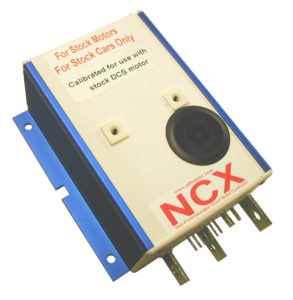

NCX STOCK or OEM Products for SHUNT Wound Electric Motors
The NCX product line are Non-Programmable Controllers used with motors. These units are designed specifically for factory equipped golf cars.
Customers demanded higher quality after-market replacement with a warranty instead of “REBUILT USED Controllers”. Alltrax stepped up and designed a NEW product with a NEW warranty, the NCX Non-Programmable controllers. A cost effective solution to replace your aging or damaged stock controller without buying a “rebuilt controller”.
- Programmable via RS232 comm port using PC or Laptop
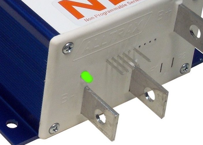
- Integrated anodized heat-sink with multi bolt pattern for flexibility
- Fully encapsulated epoxy fill – environmentally rugged design
- Available in 300 through 650 amp Performance versions
- Advanced MOSFET power transistor design for excellent efficiency and power transfer
- ½ Speed reverse option and “Plug Brake” options available
Features include:
- Factory Programmed (These are not field programmable by the customer)
- Integrated anodized heat-sink with multi bolt pattern for flexibility
- Fully encapsulated epoxy fill – environmentally rugged design
- Advanced MOSFET power transistor design for excellent efficiency and power transfer
- 1/2 Speed reverse
- Reverse Beeper Output
To view applications – visit our DCX Page