An Advanced Motor Controller for Today’s Demanding Markets

  • Thermal plastic enclosure ABS
  • 36 or 48 volt models
  • 300, 400 or 500 amp models
  • Standard connectors for Club Car, EZGo, Yamaha G19/G22 and YDRE
  • Flexible USB programming
  • Integrated heatsink mounts on any suitable surface
  • Solenoid Control Output for “Main DC Contactor Control”
  • Universal-Mount for no drill install included with Yamaha and EZ-GO controllers
  • Auto-throttle calibration for smooth operation
  • Hi-Reliability Optional Fan panel (Included on 500 amp model)
  • Compatible with our FN-K2 and FN-KS boxes to make performance adjustments in real time.
DOWNLOAD SPEC SHEET

(XCT48500G19/G22 OEM Shown)

Features & Options

Hi-Perfomance 32bit CPU

Throttle control for smooth operation compatible for most types of vehicle throttles.

Unsurpassed control with user adjustable from smooth to neck snapping wild!

USB 2.0 Programming Port

Windows XP through Windows 10

  • Free software
  • Simple Set-Up
  • User Friendly Controls
  • Note: Not compatible with WIN-8 RT (tablet)
5/16″ Terminals
  • B+ = POS – Battery + Motor Positive
  • B- = NEG – Battery Negative
  • J9 = M- Motor Minus Output
  • J7 & J8 = Field F1 and F2 Shunt Coil
  • SS 5/16″ hardware included)
Customer Connections

No adapters, direct connectors!

  • Club Car IQ, PD-Plus, i2, Excel
  • EZ-Go PDS, DCS, TXT48
  • Yamaha G19, G22, YDRE
  • Active solenoid control RLY relay coil driver
  • Sealed 23 pin OEM connector for select models with User 1 and User 2 control outputs
  • USB programmable using ALLTRAX toolkit
Universal Mount

Comes standard with Yamaha YDRE, G19/G22 and  EZ-GO DCS, PDS and TXT48 applications. For all EZ-GO controllers a TOW/RUN and solenoid mount bracket are also included (shown here).

Hi-Reliability Fan Panel

Optional panel for hi-temp areas for 300 and 400 amp models, fan panel included in 500 amp models. Easy to replace fan panel uses a floating dual bearing design for many years of service in harsh environments. 12v fan replaceable with simple tools. The fan is turned on when the controller reaches two thirds of its maximum rated output current or if it reaches a temperature of 50°C.

Add to Cart

$43.00Add to cart

ALLTRAX FN User Controls
  • FN-2 provides active speed+regen control for street to wild performance.
  • FNKS provides 3-profile selector switch: Normal, Street and Performance (or Child Mode) along with an adjustable REGEN knob.
Learn More About FN Here

MECHANICAL PICTURES / DRAWINGS

XCT

  • 5Dx9Wx3H-INCH
  • 300 amp
  • 400 amp
  • 500 amp

EZ-Go Universal adapter with hardware for SR on SERIES carts, and XCT on PDS, DCS, TXT-36, TXT-48 now comes STANDARD shipped with EZ orders (Aug 2015) with Solenoid and TOW/RUN switch bracket included.

Alltrax PN#
KIT-UNIV-MNT-EZGO

Club Car and Yamaha

Optional purchase for Club Car-DS models include IQ (NOT Precedent). Ships Standard issue for YDRE, G19, G22. Adapter allows for no-drill installation.

Alltrax PN#
KIT-UNIV-MNT-CC-DS
KIT-UNIV-MNT-YAMAHA

NOTE: Universal Adapter shown in RED for clarity.

Color of adapter shipped is “Alltrax Blue”

XCT

XCT Dimensions
Download Diagram
XCT Drill Template
Download Diagram

Install PDFs

EZ-GO DCS
Download Diagram
Yamaha Install
Download Diagram
Club Car DS Install
Download Diagram

2008.5 to 2018 Club Car IQ Precedent/Onward
Installation Guide

(For use with installation kit)

Installation Kit

Install Guide

Download Guide

Drill Template

Download Diagram

SPECIFICATIONS

Type: DC “SHUNT WOUND”separately excited motor comtroller
Undervoltage cutback: adjustable, 16-30 VDC
Overvoltage shutdown: adjustable

  • 30-60 VDC (48v models) 60 VDC MAX)

Operating Frequency: 18kHz
Voltage drop @100 amps: <0.18V

Control voltage KSI key switch and reverse:

  • XCT48xxx: 36-48V
  • 62VDC Max

Standby Current (Powered Up): <35mA (nom)
Reverse sense pin current: <0.02A (20mA)
Relay SOLENOID drive output current: 5 amp peak. 1.0A continuous

Throttle Input:

  • ITS (inductive, EZ-Go)
  • 0 – 1K Yamaha
  • Resistive 0 – 5K ohm ( +/- 10%) 2-wire and 3-wire
  • Restistive 5K- 0 ohm ( +/- 10%) Club Car
  • 0 – 5 volt
  • 6 -10.5 volt (Taylor Dunn)
  • USB Throttle (New – Software communication driven)
  • Absolute mode (Precision control for industrial applications)
  • Operating temperature; -20C to 85C, Shutdown at 95C

Adjustments via Alltrax Tool-Kit Software;

  • Throttle Acceleration / deceleration rate and map profile
  • Armature current limit
  • Brake current limit
  • Under / Over voltage shutdown
  • Half speed reverse
  • High pedal disable
  • Plug brake
DOWNLOAD SPEC SHEET
XCT Features:
  • All units 5/16″ Stainless Steel hard ware included
  • YDRE Yamaha 1/4-20 Stainless Steel hardware included
  • USB 2.0 compatible
  • Future Alltrax-CAN bus for displays, digital throttles, and Alltrax 48V Lithium Battery Management System
  • ABS+PC510 Flame resistant thermal plastic
  • All copper heat sinks for superior thermal transfer
  • Sealed epoxy UL-94-V0 / 5VA flame rating (Best in the industry)

Model Breakdown

Whats the Secret Decoder Ring?

XCT-48300-IQ

  • 48 – First two digits = Battery String Voltage (two digits) 48volt, 72volt, etc
  • 300 – Last three digits = amperage, 300 amp model, 500=500 amps (at 2 minutes)
  • IQ Model – Denotes Club car IQ with 16 pin connector
  • OEM Model – Denote model with 23 pin sealed connector for heavy duty extreme application

Product Manuals and Diagrams

OPERATING MANUALS

XCT Operators Manual
Download Manual
Alltrax Toolkit Software
Download Latest Version
Alltrax TOOLKIT Instruction Manual
Download Manual

WIRING DIAGRAMS

EZ-GO DCS
Download Diagram
EZ-GO PDS
Download Diagram
EZ-GO TXT48
Download Diagram
EZ-GO 1264/1268
Download Diagram
Club Car PD Plus
Download Diagram
Club Car IQ
Download Diagram
Yamaha G19/G22 GE Replacement
Download Diagram
Yamaha G22 Moric Replacement
Download Diagram
Yamaha YDRE
Download Diagram
XCT Generic with various throttles
Download Diagram

APPLICATION GUIDES

XCT Club Car
Download APP Guide
XCT EZ-GO
Download APP Guide
XCT Yamaha
Download APP Guide
AXE-DCX-SPM
to SR & XCT
Cross Reference
Download APP Guide

ALLTRAX TOOLKIT SOFTWARE

Using a standard USB printer cable to connect to the XCT, SR, SPM or SPB controller allows simple changes to configure the controller to your needs.

Monitor output with a laptop and save the data to your hard drive. Troubleshooting or modifying vehicle can be examined in real time!

LED Status Indicator

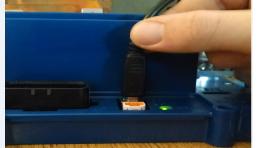
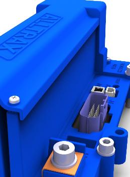
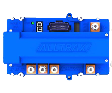
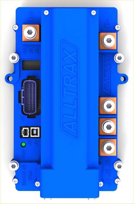
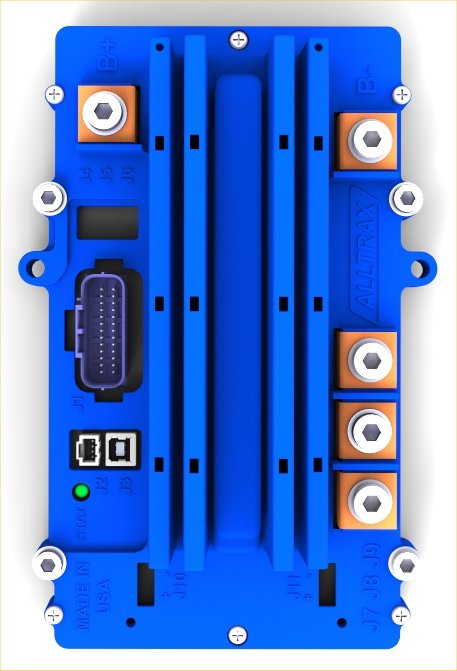
The LED located on the front of the unit provides status of the units operation and used for troubleshooting.

The LED Blink Codes occur at power up, the number of green blinks indicates the throttle configuration:

  • 1 Green LED flash = 0-5 ohm resistive
  • 2 Green LED flashes = 5k-0 ohm resistive
  • 3 Green LED flashes = 0-5 Volt
  • 4 Green LED flashes = ITS Inductive E-Z-GO
  • 5 Green LED flashes = 0-1K ohm resistive, Yamaha
  • 6 Green LED flashes = 6-10.25 Volt, Taylor-Dunn
  • 7 Green LED flashes = 5k-0 ohms, 3-wire, ClubCar
  • 8 Green LED flashes = Reserved for future use
  • 9 Green LED flashes = PUMP Mode (toggle on-off ramp to 100% output)
  • 10 Green LED flashes = USB Comm-throttle
  • 11 Green LED flashes = Absolute throttle

Normal display status:

Solid Green: Controller ready to run
Solid Yellow_ Controller throttle is wide open, controller is supplying max output, and is not in current limit

Troubleshooting:

The XCT-SRX controllers ERROR codes are different than the AXE and DCX products. Please note the Error code display: # of GREEN and RED blinks indicates any error conditions that might exist:

Critical:

  • 1-GRN (+) 1-RED LED flash = Over Current/Short Circuit
  • 1-GRN (+) 2-RED LED flash = Battery Under Voltage
  • 1-GRN (+) 3-RED LED flash = Battery Over Voltage
  • 1-GRN (+) 4-RED LED flash = Over Temp (Check connections)
  • 1-GRN (+) 5-RED LED flash = Motor Field OPEN alarm (Check connections)
  • 1-GRN (+) 6-RED LED flash = Pre-Charge Failure

Status Indicator:

  • 2-GRN (+) 1-RED LED flash = Under Temp (below -20C)
  • 2-GRN (+) 2-RED LED flash = Not Used (Reserved)
  • 2-GRN (+) 3-RED LED flash = High Throttle Over-range (note 1)
  • 2-GRN (+) 4-RED LED flash = High Throttle Under range (note 1)
  • 2-GRN (+) 5-RED LED flash = Low Throttle Over range (note 2)
  • 2-GRN (+) 6-RED LED flash = Low Throttle Under range (note 2)

Note 1: High Throttle range is the “full pedal position”

  • The throttle could be faulty
  • Wiring/connectors
  • Incorrect throttle set in the program
  • Otherwise, Clear throttle auto-calibration and try again

Note 2: Low Throttle range is the pedal “at rest OFF pedal position”

  • The throttle could be faulty
  • Wiring/connectors
  • Incorrect throttle set in the program
  • Otherwise, Clear throttle auto-calibration and try again

Note 3: Uncalibrated throttle

  • May occur when a SPM or SPB controller is auto-calibrated to one electric car throttle, then moved to another electric car – or, a new throttle is replaced.
  • Clear throttle auto calibration and try again

Advanced controller have a multitude of inputs and outputs. A sequence of Green+Red provides more alarm codes without counting past 6 flashes (which is difficult to do).

There is a pause between these alarm sequences always starting with GREEN.

Group 1: 1-Green + Red alarm code is a Critical Alarm
Group 2: 2-Green + Red alarm code is a condition that may inhibit or cause the controller to stop, but is not a hard fault, rather a condition that requires attention.
Group 3: 3-Green + Red alarm code is an uncalibrated throttle, clear the throttle calibration and try again. The program may also have a fault or loaded or updated incorrectly. Contact Alltrax Customer support for troubleshooting Bad Vars.

Tech-Talk: Throttle Range
When the throttle is pressed and foot-switch closes and records the “zero position” of the throttle. The controller remembers the highest input and stores this as 100% throttle.
This allows throttles that are “not manually calibrated”, production variances, or slightly old and worn to provide excellent low end control and always hit 100% throttle.
This learning curve is “adaptive” with built in fail safes which means – the advanced XCT knows what the range is suppose to be for a given throttle.
So if a 0-5K resistive throttle is measuring “Out Of Range” an alarm will alert the user to verify the mechanical issues to prevent an unsafe condition.