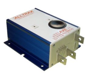
AXE Performance series and permanent magnet motor controllers
The AXE product line is used with Series Wound and Brushed Perm-Magnet Motors. These units drive golf cars, scissors lifts, boom trucks, Neighborhood electric vehicles, and a variety of other applications.
Features include:
- Programmable via RS232 comm port using PC or Laptop
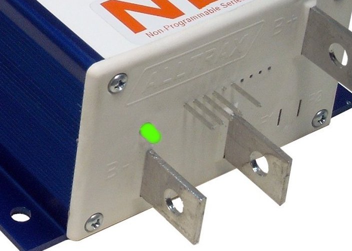
- Integrated anodized heat-sink with multi bolt pattern for flexibility
- Fully encapsulated epoxy fill – environmentally rugged design
- Available in 300 through 650 amp Performance versions
- Advanced MOSFET power transistor design for excellent efficiency and power transfer
- ½ Speed reverse option and “Plug Brake” options available

 xxx4
xxx4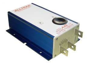 Xxx5
Xxx5